
Trailmakers Helicopter Guide: Fix Spin and Tune Lift
Build a Trailmakers helicopter with servo settings that tame rotor torque, compare blade options, and learn how to control lift without constant climbing.
Jump to

How to Stop Your Helicopter From Spinning
A Trailmakers helicopter that spins its body opposite the rotor has a torque problem. Mounting the helicopter engine on a servo can address that unwanted rotation, making lift control much easier to work on. Start with the rotor assembly before adding more complicated blades.
When a single helicopter engine drives the rotor in one direction, the body reacts by turning the other way. Increasing engine speed alone doesn’t solve that reaction torque.
Spinning Servo Setup
This servo arrangement uses a Spinning Servo beneath a Stackable Helicopter Engine:
- Place a Spinning Servo beneath the rotor assembly.
- Attach a Stackable Helicopter Engine on top.
- Set the Spinning Servo’s speed to 0.
- Leave the helicopter engine at its default settings while checking the assembly.
The zero-speed setting belongs to the servo. The helicopter engine still needs to drive the blades. You can increase the engine’s speed separately.
Rotating Servo Setup
A Rotating Servo provides another mounting option. Place it beneath the helicopter engine and configure it as follows:
| Rotating Servo setting | Value |
|---|---|
| Speed | 0 |
| Angle | Infinity |
| Strength | 0 |
| Damping | Default |
Leave the helicopter engine unchanged initially. As with the Spinning Servo arrangement, the servo settings and engine speed serve different purposes.
Combining Both Servos
You can also combine a Spinning Servo and a Rotating Servo, retaining the settings above. This arrangement has an extra connection requirement: connect the top of the Spinning Servo to the center of the helicopter engine.
That center connection matters because it is the engine’s driven rotating section. If the combined assembly activates but the blades remain stationary, inspect that connection before changing engine power.
Build and check the simpler arrangements separately before combining them. That keeps a connection problem from getting mixed up with a configuration problem.
Official page: Trailmakers (playtrailmakers.com)
Choose Blades Around Your Lift Controls
Stopping body rotation and controlling altitude are separate jobs. Your blade choice determines how you adjust lift once the rotor is working.
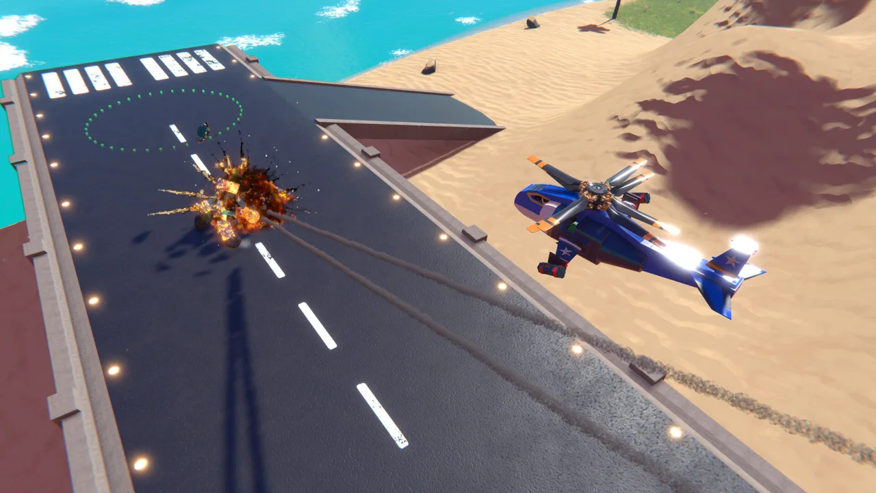 Image: Steam / Flashbulb
| Blade construction | Lift behavior | How you adjust it |
|---|---|---|
| Standard Helicopter Blades | Produce lift while spinning | Change rotor speed |
| Custom wings with flaps | Can change lift while the rotor keeps spinning | Adjust the flaps |
| Decorative shield pieces | Do not produce lift in the cosmetic rotor example | Provide lift through another part of the build |
Standard Helicopter Blades
Standard blades provide a straightforward lifting rotor, but they don’t give you adjustable blade pitch. With simple on/off engine input, the helicopter climbs while powered and loses lift when you cut power.
You can still adjust lift through rotor speed. Controller input allows direct speed adjustment, while a keyboard setup can use an accumulator for adjustable engine input. Avoid treating the stock blades as strictly binary if your control setup supports finer speed changes.
Custom Wings and Flaps
Custom blades built from wing pieces and flaps let you adjust lift without stopping the rotor. In the demonstrated arrangement, the neutral flap position produces no lift, moving the flaps downward creates lift, and the opposite input lowers altitude.
Set separate controls for engine activation and flap movement. Keeping those functions independent lets you change lift while the blades continue turning.
Custom wing blades also introduce drag. If the helicopter leans in the rotor’s direction of rotation, address that behavior separately from the body spinning around its vertical axis.
Decorative pieces need the same distinction. Shield pieces can create the appearance of rotor blades, but the shield rotor described here supplies no lift itself.
Address Custom Blade Drag With Detachable Blocks
The drag-glitch technique uses temporary covering blocks attached through Detachable Blocks to suppress drag on the blades. It targets the drag-related tilt associated with custom rotors.
To assemble it:
- Add a Detachable Block and attach covering blocks to it.
- Position those blocks so they cover the aerodynamic arrows pointing toward the blade blocks.
- Cover the relevant blade side based on the direction the rotor spins.
- Connect a logic gate to all the Detachable Blocks so they detach when the creation spawns.
- Enable Make Scrap on the Detachable Blocks.
Placement follows the rotor’s direction. Copying the coverings onto the same side of a rotor that spins the opposite way misses that detail.
Keep this adjustment separate from the servo mount. The servo arrangement addresses reaction torque; the detachable covering arrangement addresses blade drag. Change one assembly at a time so you can identify which behavior you’re correcting.
Check Engine Bindings Before Flying
Older builds can be confusing when their controls differ from the current defaults. The June 17, 2025 update changed the keyboard defaults for both helicopter engine types:

- Helicopter Engine: Space and CTRL replaced W/S.
- Stackable Helicopter Engine: Space and CTRL replaced W/S.
- Custom bindings: Existing customized inputs stayed unchanged.
Inspect each engine’s configuration before assuming a downloaded helicopter uses the default controls. For custom wing rotors, check the flap bindings separately from the engine inputs.
Use Community Blueprints to Explore Other Designs
The Steam version includes Steam Workshop support, giving you another way to explore vehicle layouts. Inspect the rotor mount, blade construction, and control assignments individually when opening someone else’s helicopter.
Helicopters also featured in the City Life Build Challenge:
- On October 22, 2026, a Police Helicopter was announced as the Engineer League winner.
For the downloadable City Life blueprint pack, the Windows installation steps are to extract the ZIP, copy the entire extracted folder, and paste it into C:\Users\%username%\Documents\TrailMakers\Blueprints. The blueprints should then appear in the game.
Continue with
 Trailmakers Mech Guide: Build a Stable Walking BaseBuild a Trailmakers mech with stable leg cycles, smoother suspension, and better slope traction. Learn what Mech Amok adds and how to shape a walking base.
More in Builds
Trailmakers Go Kart: Build and Tune a Stable Racer
Build a Trailmakers go kart with a low chassis, balanced weight, and responsive steering. Learn how tire settings and rear downforce shape its handling.

Trailmakers Motorcycle Guide: Build and Tune 3 Bikes
Build a Trailmakers motorcycle with precise gyro settings, tire traction values, and working lights. Make a cafe racer, bagger, or superbike of your own.
Continue exploring
Trailmakers Mods: Workshop Setup and Creative Tools
Explore Trailmakers mods with Steam Workshop setup, block editing, custom tracks, and practical fixes for crashes, map conflicts, and lingering gravity.
Trailmakers Build Mode: Build Better Cars and Planes
Master Trailmakers build mode with useful tips for symmetry, hinges, pistons, and vehicle shaping. Build cleaner boats, planes, and cars with fewer errors.
Join the community
Official channels for news, updates and player help: